Why Digital Controllers Should Synchronize with Camera Triggers
Summary: Understand why digital lighting controllers should synchronize with camera exposure to reduce blur, ambient interference and unstable inspection images.
Why timing matters
Digital lighting controllers are used to manage brightness, channel output, strobe duration and switching logic in machine vision systems. When they operate independently from the camera, the inspection image may change from cycle to cycle. A part can move during exposure, ambient light can leak into the image, or the light may reach full output slightly before or after the camera captures. Synchronization solves this by aligning the lighting event with the camera trigger.
In high-speed production, even a small timing mismatch can cause motion blur or inconsistent contrast. This is especially obvious when the line uses short exposure times, multiple light angles or reflective parts. A synchronized controller allows the system to produce a strong pulse of light only when the camera needs it.
Benefits of synchronized control
The first benefit is repeatability. When the controller and camera respond to the same trigger sequence, every image is captured under a known lighting condition. This improves measurement stability and reduces variation in code reading, edge detection and surface inspection. The second benefit is reduced ambient-light influence. Short strobe timing can overpower background light and make the inspection less sensitive to factory lighting changes.
The third benefit is thermal and electrical efficiency. Instead of running LEDs at high brightness continuously, the system can apply a controlled pulse during exposure. This may reduce heat load and support brighter instantaneous illumination where the light and controller are designed for that use.

Integration points to check
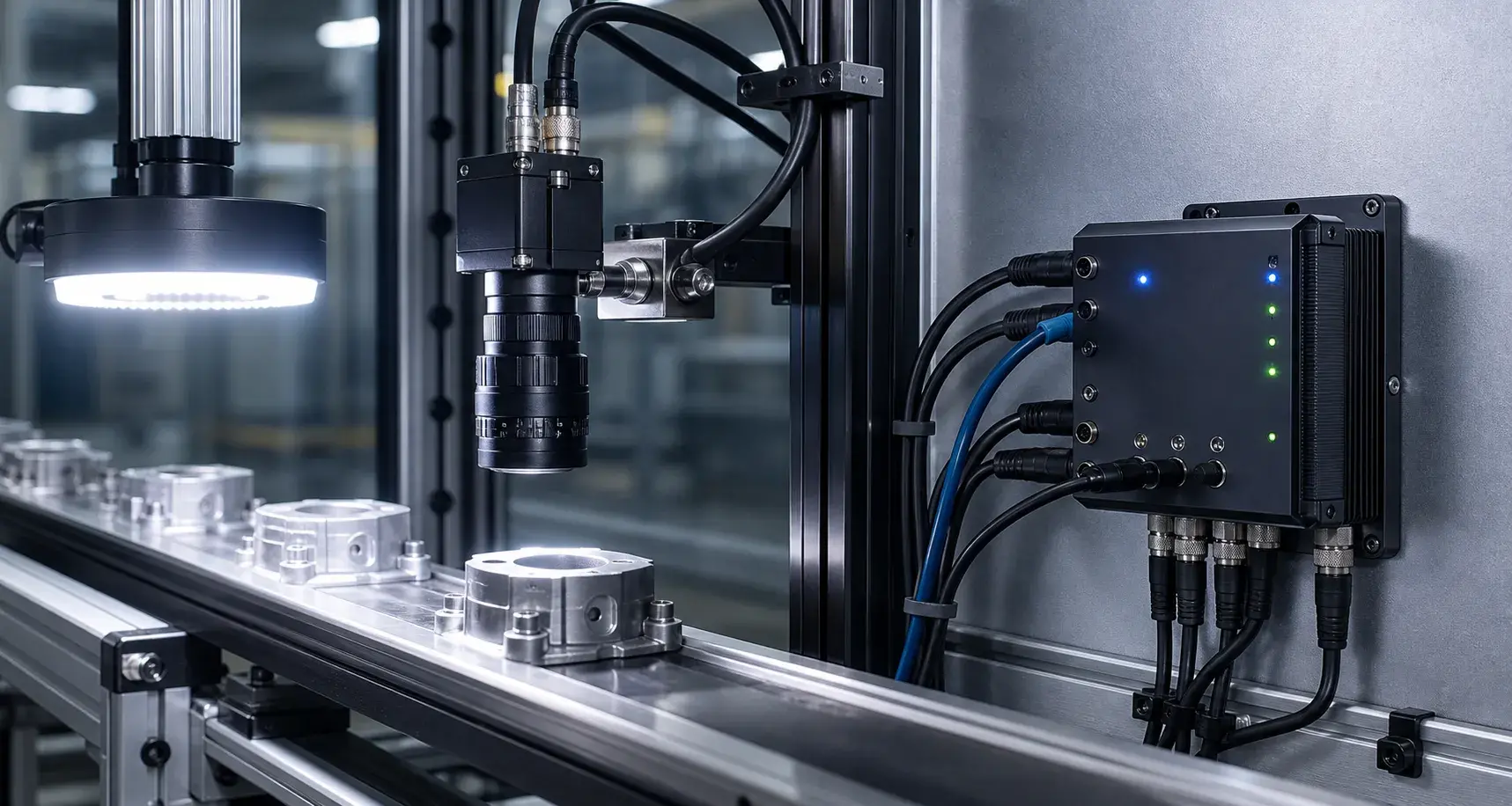
During integration, engineers should confirm trigger type, voltage level, response time, channel count and output current. If several lights are used in one station, each channel may need a different delay, brightness or duration. The camera exposure, light pulse and part position must be tested together. The controller should also provide clear wiring and stable connectors because intermittent connections can look like software instability during troubleshooting.
For inspection stations that change product models, saved lighting recipes can improve setup efficiency. A digital controller that supports repeatable settings helps operators return to validated brightness levels after maintenance or product changeover.
A useful commissioning method is to document one timing chart for every inspection mode. The chart should include sensor signal, controller output, light pulse width, camera exposure and image acquisition result. This record gives electrical engineers, vision engineers and maintenance technicians the same reference when the station is adjusted later. It also reduces the risk of changing one setting without understanding how it affects the rest of the inspection cycle.
Conclusion
Synchronization is not only a technical detail. It is a practical way to make every inspection image more repeatable. When the controller, camera and sensor work on the same timing plan, a machine vision station becomes easier to commission, easier to maintain and more reliable in daily production.
Practical Checklist
- Confirm trigger voltage, timing and response delay.
- Match output current and channel count to the light sources.
- Save validated brightness settings for maintenance.